The modular design of our our overload relays allows for direct mounting onto contactors providing complete 3 phase motor overload protection.
Introduction to Motors
Electric motors are an integral component of industrial equipment, toys, vehicles, and electronic devices. They are designed to convert electrical energy into mechanical energy. These devices may be powered by AC or DC sources. Blowers, fans, compressors, cranes, extruders, and crushers are a few important devices equipped with electric motors.
What is an Induction Motor?
An induction motor, also referred to as a synchronous motor, is one of the main types of AC electric motors used in commercial and industrial environments. These motors feature armortisseur windings, and work on the principle of electromagnetic induction. The electro-magnetic field in the rotor is produced by the rotating field of the stator. In short, the power is transferred to the rotor winding by stator through induction. There are two main types of induction motors — single-phase induction motors and three-phase induction motors.
Single Phase Induction Motor
A Single-Phase Induction Motor is an electric motor commonly used in household appliances and light industrial equipment. It operates on a single-phase power supply, which means it uses one alternating current (AC) voltage. This type of motor has a simple design with two main parts: a stationary part called the stator and a rotating part called the rotor. The stator generates a magnetic field when connected to power, which induces a current in the rotor, causing it to turn.
Single-phase induction motors are known for their reliability, low cost, and ease of maintenance, making them ideal for use in fans, pumps, refrigerators, and other small machines. However, they are generally less efficient and powerful compared to three-phase motors.
Introduction to Three-Phase Induction Motors
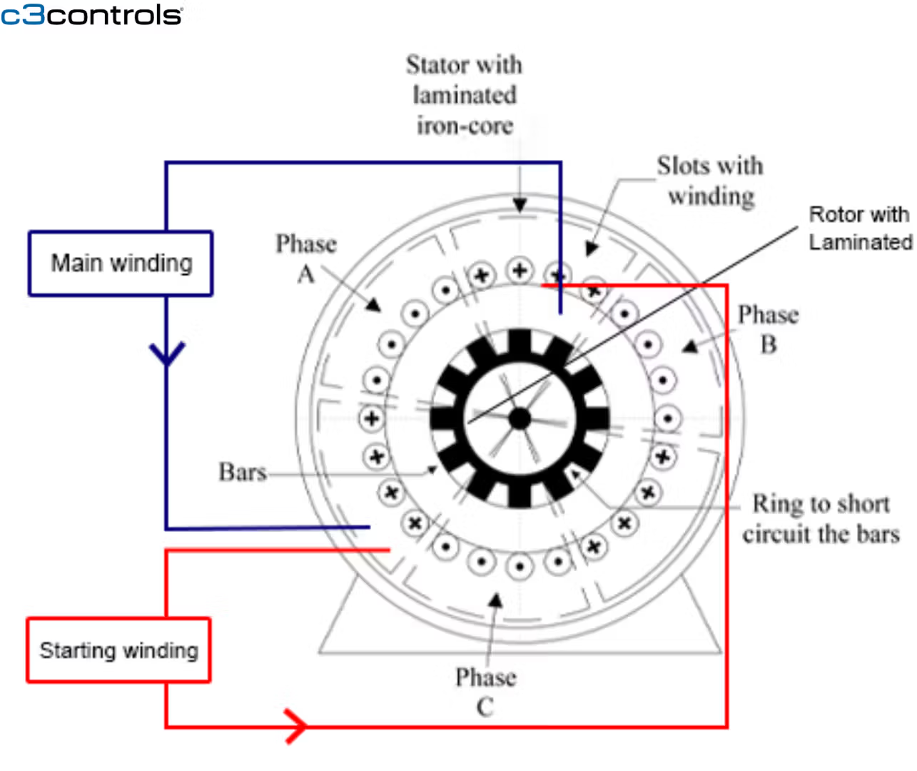
It is one of the most widely used types of electrical motors; and, is an integral part of almost 80% of the industrial applications. Its popularity is due to the rugged construction, excellent operating characteristics, speed regulation, and absence of commutator. Like any regular induction motor, this motor also comprises a stator and rotor.
- Stator: This is the stationary element of the induction motor. The stator is a small cylindrical frame which carries the cylindrical core of the rotor. It features different slotted stampings to carry three-phase windings. The windings of the stator have 120 degrees separation.
- Rotor: This is the rotating part of the motor. The rotor features laminated cylindrical slots with copper or aluminum conductors that have joined ends. It is the shaft of the motor.
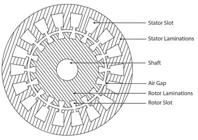
The rotor of the three-phase induction motor is classified as phase wound rotor or slip ring rotor and squirrel cage rotor. Among the two, the squirrel cage rotor is one of the most common ones.
Squirrel Cage Induction Motors
Induction motors equipped with a squirrel cage rotor are known as squirrel cage induction motors. They get their name because the rotor resembles the rotating cylindrical “cage” that you might find in a pet squirrel or hamster cage. These motors are available in sizes ranging from fractional horsepower (HP) less than one kilowatt to 10,000’s HP (tens of megawatts). Factors such as simplicity, rugged construction, and constant speed in different load sizes have contributed to their popularity. Like other induction motors, the squirrel cage motor consists of:
- Rotor: It is a cylindrical-shaped component mounted on a shaft. It contains longitudinally organized conductive bars. The bars are made of copper or aluminum, and are set into grooves, which are connected at ends to form a cage-like structure. The rotor has a laminated core, which helps avoid power loss due to hysteresis and Eddy currents. Conductors of the rotor are skewed, which helps prevent cogging during the start of the equipment. Also, this skewing assures improved transformation ratio between the rotor and stator.
- Stator: It consists of a three-phase winding along the core. The stator is placed in a metal housing. The windings in the stator are organized such that they are 120-degree apart in space, and mounted on a laminated iron core. This iron core provides reluctance path for flux generated by AC currents.
What is Overload Protection?
When the motor draws excess current, it is referred to as an overload. This may cause overheating of the motor and damage the windings of the motor. Because of this, it is important to protect the motor, motor branch circuit, and motor branch circuit components from overload conditions. Overload relays protect the motor, motor branch circuit, and motor branch circuit components from excessive heat from the overload condition.
Overload relays are part of the motor starter (assembly of contactor plus overload relay). They protect the motor by monitoring the current flowing in the circuit. If the current rises above a certain limit over a certain period of time, then the overload relay will trip, operating an auxiliary contact which interrupts the motor control circuit, de-energizing the contactor. This leads to the removal of the power to the motor. Without power, the motor and motor circuit components do not overheat and become damaged. The overload relay can be reset manually, and some overload relays will reset automatically after a certain period of time. After which, the motor can be restarted.
Basic Components of Overload Relays
- Current Sensing Element: This component detects the amount of electrical current flowing through the circuit. It can be a bimetallic strip, magnetic coil, or electronic sensor, depending on the type of relay.
- Thermal sensing element: This detects the heat generated by the heater element and responds accordingly. Common types include bimetallic strips, eutectic alloys, or electronic sensors.
- Tripping Mechanism: This part is activated when the current exceeds a safe level, causing the relay to open the circuit and cut off power to protect the motor or system.
- Reset Mechanism: After tripping, the relay needs to be reset, either manually or automatically, to restore the circuit. This allows the system to be restarted once the issue causing the overload is resolved.
- Auxiliary Contacts: These are additional contacts that can signal other parts of the system, such as alarms or indicators, when the relay trips. They help in monitoring the status of the relay and the connected equipment.
- Adjustment Controls: Many overload relays have settings that allow users to adjust the trip point or sensitivity to suit specific applications and motor ratings.
Key Benefits of Overload Relays:
Overload relays offer several key benefits:
- Protection from Damage: Overload Relays prevent motors and electrical equipment from overheating and getting damaged due to excessive current, ensuring longer equipment life.
- Safety: By cutting off power during overload conditions, they reduce the risk of fires and other safety hazards.
- Cost Savings: Overload Relays help avoid expensive repairs and replacements by protecting motors and equipment from being damaged.
- Automatic Response: It automatically detects and responds to overload conditions, which means they can protect equipment without needing constant monitoring.
- Adjustability: Many overload relays allow users to set the trip current level, making them versatile for different applications and motor sizes.
- Reliability: Overload Relays provide consistent protection, even in environments with fluctuating temperatures or varying loads, ensuring the equipment operates safely.
How an Overload Relay Works
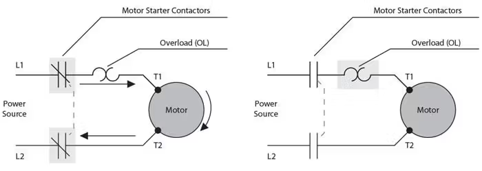
The overload relay is wired in series with the motor, so the current that flows to the motor when the motor is operating also flows through the overload relay. It will trip at a certain level when there is excess current flowing through it. This causes the circuit between the motor and the power source to open. The overload relay can be manually or automatically reset after a predetermined time duration. The motor can be restarted after the cause of the overload has been identified and rectified.
Types of Overload Relays
Bimetallic Overload Relay
Many overload relays include bimetallic elements or bimetallic strips, also referred to as heater elements. The bi-metallic strips are made of two types of metals – one with a low coefficient of expansion, and another with a high coefficient of expansion.These bimetallic strips are heated by a winding around the bimetal strip, which carries the current. Both of the metal strips will expand due to the heat. However, the metal with a high coefficient of expansion will expand more in comparison to the metal with a low coefficient of expansion. This dissimilar expansion of the bimetallic strips causes the bimetal to bend towards the metal with a low coefficient of expansion.As the strip bends, it actuates an auxiliary contact mechanism and causes the overload relay normally closed contact to open. As a result, the contactor coil circuit is interrupted.The amount of heat generated can be calculated by the Joule’s Law of Heating. It is expressed as H ∝ I2Rt.
- I is the overcurrent flowing through the winding around the bimetal strip of the overload relay.
- R is the electrical resistance of the winding around the bimetal strip.
- t is the time period for which the current I flows through the winding around the bimetal strip.
The above equation defines that heat produced by the winding will be directly proportional to the time period of the flow of overcurrent through the winding. In other words, the lower the current, the longer it will take the overload relay to trip and the higher the current, the faster the overload relay will trip, in fact it will trip much faster because the operation of the relay is a function of the current squared.
Bimetallic overload relays are often specified when automatic reset of the circuit is required, and occurs because the bimetal has cooled and returned to its original state (form). Once this happens the motor can be restarted. If the cause of overload is not rectified, the relay will trip again, and reset at predetermined intervals. It is important to be careful during the selection of an overload relay, because repeated tripping and reset can reduce the mechanical life of the relay and may cause damage to the motor.
In many applications, the motor is installed at a location with a constant ambient temperature, and the overload relay and motor starter may be installed in a different location, which experiences different ambient temperatures. In such applications, the trip point of the overload relay can vary depending on multiple factors. The current flow through the motor and the temperature of the surrounding air are two factors, which may cause premature tripping. In such cases, ambient compensated bimetallic overload relays are used. The relays of this type feature two types of bi-metal strips – a compensated bi-metal strip and a primary non-compensated bi-metal strip. At ambient temperatures, both these strips will bend equally, thereby preventing the overload relay from nuisance tripping. However, the primary bi-metal strip is the only strip that gets affected by the current flow through the heater element and the motor. In the condition of an overload, the trip unit will be engaged by the primary bi-metal strip.
Eutectic Overload Relay
This type of overload relay is comprised of a heater winding, a mechanical mechanism for activation of a tripping mechanism, and a eutectic alloy. A eutectic alloy is a combination of two or more materials, which solidifies or melts at a specific known temperature.
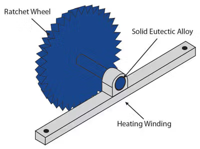
In the the overload relay, the eutectic alloy is contained in a tube, which is often used along with a spring loaded ratchet wheel to activate the tripping mechanism during the overload operations. The motor current passes through the small heater winding. During the overload, the eutectic alloy tube is heated by the heater winding. The alloy melts due to the heat, thereby releasing the ratchet wheel, and allowing it to turn. This action initiates the opening of the closed auxiliary contacts in the overload relay.
Eutectic overload relays can only be manually reset after tripping. This reset is usually done through a reset button, which is positioned on the cover of the relay. The heater unit installed on the relay is chosen on the basis of the full load current of the motor.
Solid State Overload Relay
These relays are commonly referred to as electronic overload relays. Unlike the bimetallic and eutectic overload relays, these electronic overload relays measure current electronically. Although available in various designs, they share common features and benefits. The heaterless design is one of the main advantages of these relays. This design helps reduce the costs and efforts of installation. In addition, the heaterless design is insensitive to the change in ambient temperatures, which helps minimize nuisance tripping. These relays also provide protection from phase loss – more effectively than bimetallic or eutectic alloy overload relays. These relays can easily detect a loss of phase, and operate an auxiliary contact to open the motor control circuit. Solid state overload relays enable easy adjustment of trip times and set points.
Solder Pot Thermal Overload Relays
A Solder Pot Thermal Overload Relay is a device used to protect electrical circuits from overheating. It has a small metal pot filled with a special solder that melts when the temperature reaches a certain level. When too much current flows through the circuit, a heating element heats up and melts the solder. This melting action triggers the relay to open and cut off the power, preventing damage. After it trips, the relay must be manually reset before the circuit can be used again. It’s a simple and cost-effective way to protect electrical systems, though it may not respond as quickly as more modern electronic relays.
Magnetic Overload Relay
A Magnetic Overload Relay is a device used to protect electric motors and circuits from damage due to excessive current. It operates by using a magnetic coil that generates a magnetic field proportional to the current flowing through it. When the current exceeds a preset limit, the magnetic field becomes strong enough to trigger a mechanism that opens the relay, cutting off the power to the motor or circuit. This action prevents overheating and potential damage.
Magnetic overload relays are known for their quick response to sudden overcurrent conditions, making them effective for protecting against short circuits and other rapid changes in current. They are often adjustable, allowing the user to set the trip current according to the specific requirements of the application.
Electronic Overload Relay
Electronic Overload Relays are devices designed to protect electric motors and circuits from damage due to excessive current or overheating. Unlike traditional thermal or magnetic overload relays, electronic overload relays use electronic components to monitor the current flowing through the circuit. They can precisely detect overcurrent conditions and respond quickly to protect the system. These relays often feature adjustable settings, allowing users to set specific trip points for different applications. They are less sensitive to changes in ambient temperature, which helps prevent false trips.
Additionally, electronic overload relays can offer advanced features like phase loss protection, which guards against the risk of motor damage when one phase of the power supply fails. Their reliability and precision make them suitable for modern industrial and commercial applications where accurate motor protection is critical.
Ambient Compensated Overload Relay
An Ambient Compensated Overload Relay is a type of overload protection device designed to provide consistent and accurate protection for electric motors, regardless of changes in the surrounding temperature. Unlike standard overload relays, which can be affected by ambient temperature fluctuations, ambient compensated overload relays include a special mechanism that adjusts for these temperature changes.
This ensures that the relay will trip at the correct current level, even if the environment becomes significantly hotter or colder. This feature helps prevent nuisance trips in varying temperatures and provides more reliable protection for the motor and associated equipment. These relays are particularly useful in environments where temperatures can vary widely, ensuring that the motor is protected under all conditions.
Overload Relay Tripping
The tripping time of an overload relay will decrease when the current increases. This function is plotted on the inverse time curve below, and is termed as the trip class. The trip class also indicates the time taken by the relay to open in an overload condition.
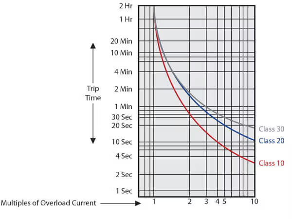
Trip Classes 5, 10, 20, and 30 are common. These classes suggest that the overload relay will trip in 5, 10, 20, and 30 seconds. This tripping usually occurs when the motor is running 720% of its full load. Trip Class 5 is suited for motors that demand fast tripping, whereas Class 10 is usually preferred for motors of low thermal capacity like submersible pumps. Class 10 and 20 are employed for general purpose applications, whereas Class 30 is employed for loads with high inertia. Class 30 relays help avoid nuisance tripping.
We hope that this short paper has given you a good, basic understanding of overload relays. Look for other informative papers from c3controls at c3controls.com/blog.
Disclaimer:
The content provided in this white paper is intended solely for general information purposes and is provided with the understanding that the authors and publishers are not herein engaged in rendering engineering or other professional advice or services. The practice of engineering is driven by site-specific circumstances unique to each project. Consequently, any use of this information should be done only in consultation with a qualified and licensed professional who can take into account all relevant factors and desired outcomes. The information in this white paper was posted with reasonable care and attention. However, it is possible that some information in these white papers is incomplete, incorrect, or inapplicable to particular circumstances or conditions. We do not accept liability for direct or indirect losses resulting from using, relying or acting upon information in this white paper.
ISO 9001:2015
Certified
17+ Million Product
Configurations
Lifetime
Warranty
Guaranteed
Same-Day Shipping
Advantage Pricing
Save Up To 40%
c3controls Headquarters, USA
664 State Avenue
Beaver, PA 15009
